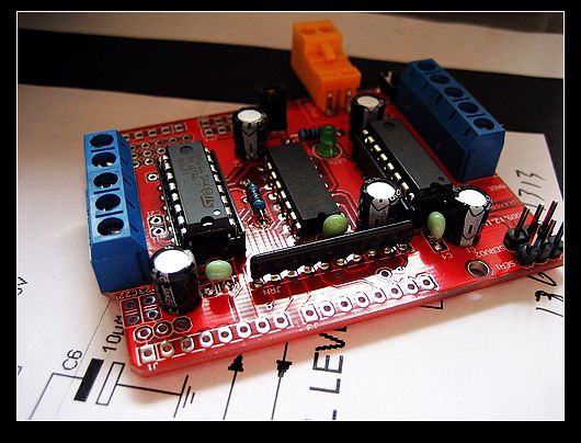
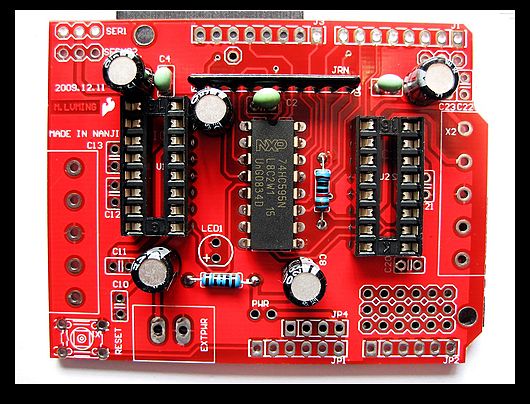
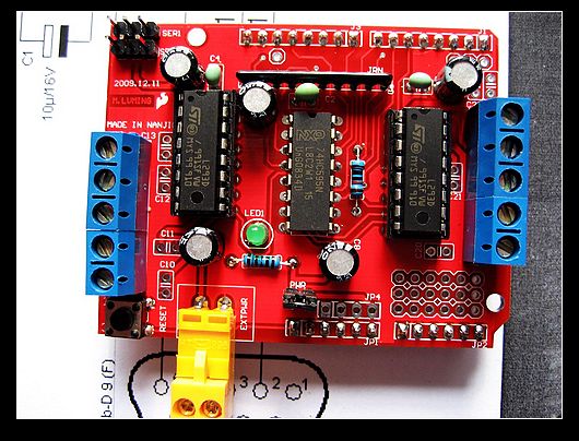
This is a finished motor drive board.
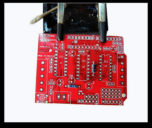
You need a 25W electric soldering iron and a roll of solder wire
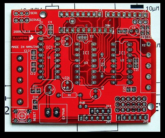
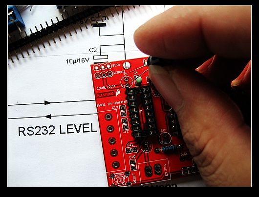
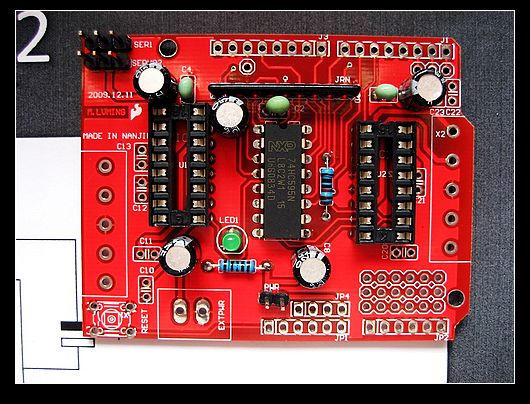
OK. Let's began. As the following map. This is a PCB board where you weld all the components.
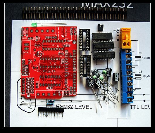
The following pic shows all the components you need.
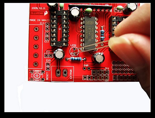
First, solder the two resistaces. It's simple:
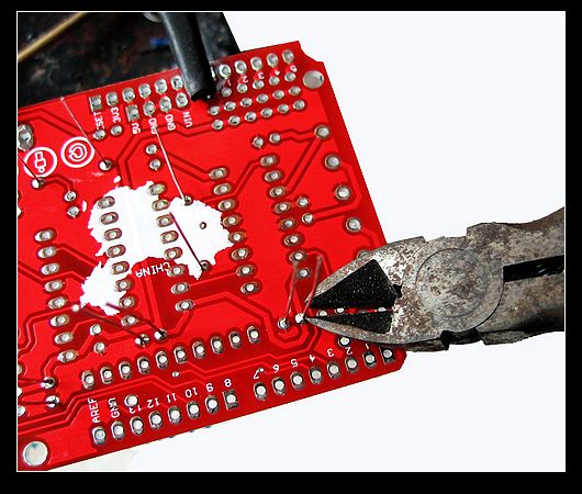
Cut the long foots:
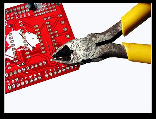
Then weld there capacitors and cut the foots as above:
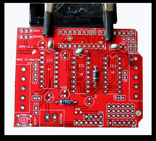
Now weld the exclusion. Which is exclusion? That black thing below. Exclusion has polarities. The foot facing the white point is GND. Weld it in the right position as following do:
finished:
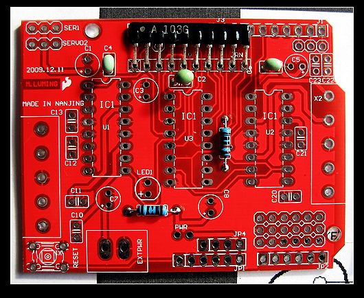
Now we begin welding 74HC595. The IC chip also has direction with the gap up. Install it as the following pic and weld it on.
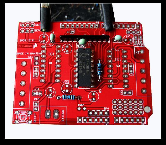
Now we weld IC transposon beside 74HC595. Pay attention to the direction.
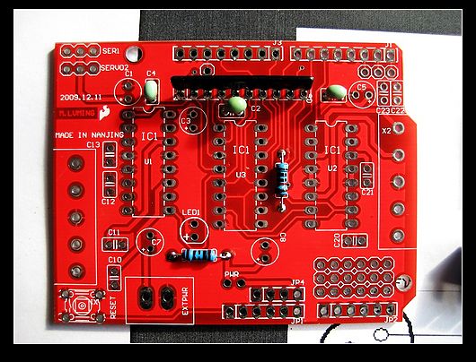
Now we begin to weld electrolytic capacitors. Electrolytic capacitor has positive and negative polarities. The long legs is positive. Note that the hole with the + sign on the billboard is positive. Match the capacitor's polarities with the board's.
There are five capacitors on the boards:
cut the foots:
The next is LED diode. Pay attention to positive and negative polarities.
cut the foots:
Weld the two foot terminals for steering gear on the top-left board:
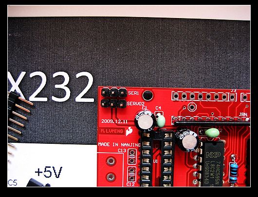
Weld the foot terminals for power (PWR):
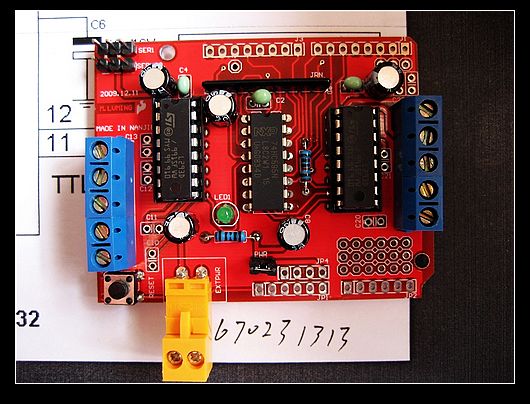
As following, weld the two blue output terminals, the yellow power terminal, and reset switch. Then install the two L239 as on the pic.
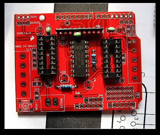
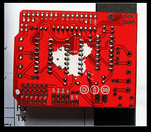
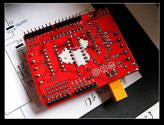
At last, weld the pins on the back of the board:
OK, all is down:
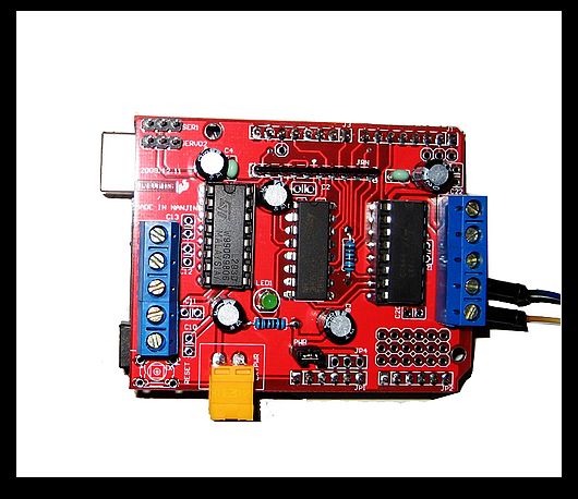
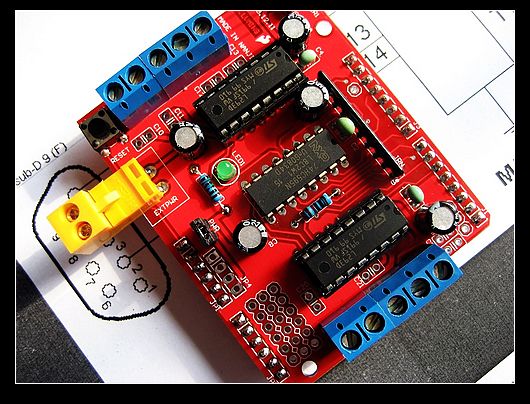
Now this baord can work without any debugging . It can simultaneously drive two steering gears and four DC motor (PWM can adjust speed). It can drive two stepper motors and connect to four sensors. Of course it has to work with Arduino control board.

No comments:
Post a Comment